
1) Tools you’ll need
- Digital multimeter (DMM) with AC voltage, DC voltage, continuity, and ohms.
- Clamp/inline ammeter (optional, helpful).
- Insulation resistance tester (megger) if available (very helpful).
- Capacitance meter or a DMM that measures capacitance (for capacitor motors).
- Non-contact voltage tester (for a quick presence check).
- Basic hand tools (screwdrivers, nut drivers, pliers, electrical tape).
- Flashlight, small mirror.
- Lockout/tagout gear and gloves, safety glasses.
- Notebook and camera (take photos of wiring before disconnecting).
2) Understand the motor and the circuit (quick fundamentals)
- Single-phase motor types you’ll commonly see: split-phase (capacitor start or capacitor start/run), PSC (permanent split capacitor), shaded pole. Many small motors (120 V) use one hot and one neutral; larger may use two hots for 240 V (no neutral).
- Nameplate: always read the motor nameplate — it gives voltage, current (amps), horsepower, phase, and sometimes wiring diagram and capacitor value. This is your primary reference.
- Typical US branch-circuit wire colors: hot = black (or red), neutral = white, equipment ground = green or bare. Don’t rely only on colors — always test.
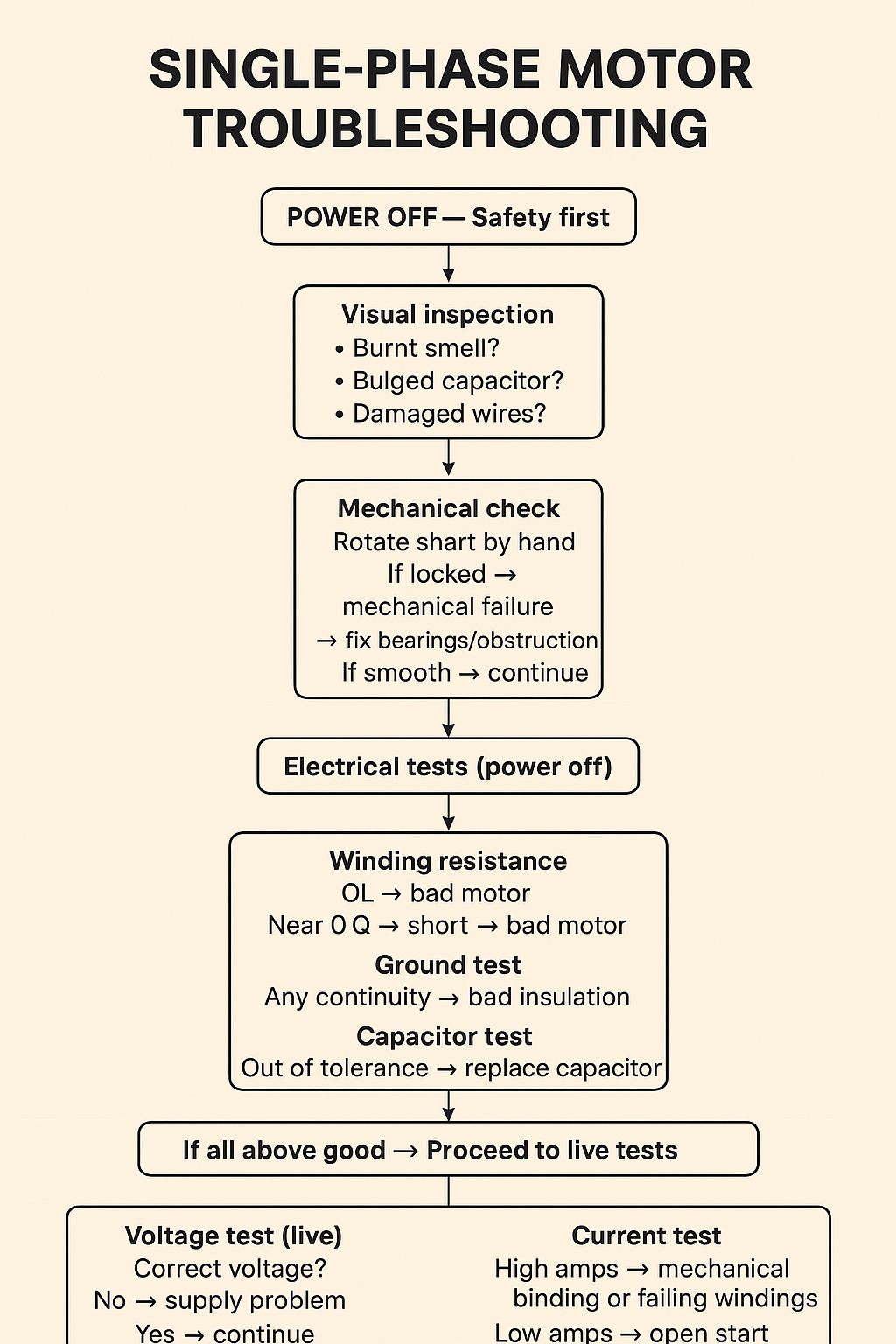
3) Visual inspection (first, with power off)
- Turn power OFF and lockout/tagout.
- Inspect the motor housing, wiring, and connections:
- Burn marks, melted insulation, discoloration, oil or water entry.
- Loose terminal screws or corroded terminals.
- Damaged capacitors (bulged top or leakage).
- Worn or seized shaft / bearings (try to rotate shaft by hand — should turn smoothly).
- Smell check: burnt windings smell sharp and acrid — that’s a warning.
- Check for mechanical obstruction: fan blades hitting housing, coupling misalignment.
If you see obvious damage (melted wiring, burnt windings), don’t reconnect — that motor probably needs repair or replacement.
4) Identify which wire is which (neutral, hot, ground)
Important: Do this with power OFF for continuity checks, or with power ON for voltage checks only if you know what you’re doing and take safety precautions.
A. With power ON (safe procedure if comfortable):
- Use a DMM set to AC volts.
- If you think a conductor is neutral: measure between that conductor and ground — the neutral will read close to 0 V (a few volts at most); a hot will read ~120 V (U.S. 120V circuit) or ~240 V (between two hots).
- Example: Suspected hot to ground ≈ 120 V → hot. Suspected neutral to ground ≈ 0–2 V → neutral.
- On 240 V single-phase circuits there may be 2 hots and no neutral: measure between the two suspected hots → ~240 V; each hot to ground ≈ 120 V.
B. With power OFF:
- Visually follow and trace wires back to the disconnect or panel where possible (best).
- Use continuity on the DMM (power OFF) to check continuity between the suspect neutral and the neutral bus in the panel (with both ends accessible). If it rings (low ohms) it’s neutral.
- Do not rely solely on wire color — previous work may have used wrong colors.
C. Non-contact voltage testers: they tell you “voltage present” but not which conductor is neutral reliably. Use for a quick presence check only.
5) Basic sequence of tests (order matters)
Follow this order. Tests 1–3 are non-invasive and low risk after power off (except live voltage checks which must be done carefully).
A. Confirm supply voltage (live)
- With power ON and using PPE, measure voltage at the motor supply terminals:
- L1 to L2 (or hot to neutral) should match the motor nameplate (e.g., 120 V or 240 V).
- If voltage is missing or low, the problem may be upstream (breaker, fuses, contactor).
- If supply voltage is correct, proceed.
B. Check for mechanical issues
- With power OFF, try to rotate the shaft by hand. If it’s locked or rough, the motor may be mechanically seized (bearing failure, jam, coupling failure).
- If motor seized → don’t energize. Bearings or mechanical repair needed.
C. Test motor windings (power OFF) — use DMM (ohms)
- Disconnect motor from power and isolate it (remove wires from motor terminals).
- Identify motor terminals (e.g., U-V-W or T1-T2 etc). If a capacitor-start motor, there are start and run winding terminals.
- Measure resistance (Ω) between:
- Run winding leads (commonly between two specific terminals) — should be a small finite resistance (tens of ohms for small motors). Not open (OL) and not zero.
- Start winding leads — also finite, different value than run; usually a bit higher.
- Between start and run (they’ll show a finite resistance through the circuit).
- Expected results (rules of thumb):
- Open winding (OL) → winding is open → motor is bad.
- Very low resistance to chassis/ground (near 0 Ω) → winding shorted to ground → motor is bad.
- Very low resistance between windings (approaching 0 Ω) → shorted turns (bad).
- High but finite resistance (megΩ) → insulation breakdown — suspect.
- If you don’t have exact expected ohms, the key checks are: no opens, no shorts to ground, and difference between start and run windings (they should not be identical).
D. Insulation resistance test (recommended)
- If you have a megger, test motor windings to ground at 500 VDC (or 250 V on small motors) — nameplate may specify:
- ≥ 1 MΩ typically acceptable for older motors; new motors often > 100 MΩ. If below 1 MΩ, the insulation is degraded and motor is suspect.
- If megger not available, a DMM reading of very high resistance to ground (≫ 1 MΩ) is a good sign, but not as reliable.
E. Capacitor check (if motor uses a capacitor)
- Visually inspect the capacitor for bulging or leakage.
- Use a capacitance meter or DMM with capacitance function:
- Compare measured µF to nameplate µF on capacitor. Typical tolerance ±5–10%. If far off, replace the capacitor.
- Or substitute a known-good capacitor of the same rating briefly (with the motor disconnected from load) to see if motor starts.
F. Test start circuit (switch/centrifugal/relay)
- Many motors have a centrifugal switch or electronic relay that engages the start winding. If the motor hums but doesn’t start, suspect the start switch or capacitor.
- For motors with a mechanical centrifugal switch: check continuity across the switch when the shaft is turning (with controlled test), or inspect contacts for pitting/dirt.
G. Check overload/thermal protector and starter
- Thermal overloads or fuses in motor starters can trip. Reset or test per equipment procedure.
- Check contactor: measure coil voltage when starter is engaged; measure main contacts for continuity.
H. Current draw test (live)
- With clamp ammeter, measure running current. Compare to nameplate FLA (full load amps).
- High current while motor sluggish/hot → mechanical binding, shorted turns, or low voltage supply.
- Low/no current and motor not running → open winding or start circuit failure.
6) What specific measurements mean (quick interpretation)
- No voltage at motor terminals → supply or starter/trip issue.
- Correct supply voltage but motor won’t start and just hums → likely start circuit/capacitor/centrifugal switch.
- Motor runs but overheats or draws > nameplate amps → overload, binding bearings, wrong voltage, shorted turns.
- Open winding (OL on ohms) → winding open — motor needs rewind or replacement.
- Winding short to ground (low ohms to chassis) → unsafe — rewind or replace.
- Capacitor microfarads far below rating → start problems; replace capacitor.
- Insulation <1 MΩ on megger → degraded insulation — risk of failure/ground fault.
7) Step-by-step practical troubleshooting checklist (you can follow this at the motor)
- Stop & PPE: Turn power OFF at breaker/disconnect. Lockout/tagout. Wear PPE.
- Photo & label: Take photos of wiring, label wires before disconnect.
- Visual: Look for damage, smell, oil/water, loose wires, bulged capacitor.
- Manual spin: With power off, rotate shaft — feel for smooth rotation.
- Disconnect motor from supply for isolation.
- Ohms tests:
- Measure winding resistances between terminals.
- Measure each winding to chassis ground.
- Expect finite low ohms between winding leads, infinite (no continuity) to ground.
- Insulation test (if available): Megger windings to ground — note values.
- Capacitor test (if present): measure µF and compare to rating.
- Reconnect everything and remove lockout only when ready to test live.
- Voltage check (live) at motor terminals — confirm proper supply.
- Start test: With motor connected and unloaded (if possible), energize and observe:
- Does it start? Hums only? Trips breaker? Smoke?
- Measure current while running — compare to nameplate.
- Interpret & act:
- If open/short winding → replace motor or rewind.
- If capacitor bad → replace capacitor with same rating.
- If start switch/relay bad → repair/replace.
- If mechanical → repair bearings/coupling.
- If supply issue → fix upstream breaker/contactor.
8) Quick reference expected values and examples (very approximate)
- Small fractional HP motor run winding: tens of ohms (e.g., 5–50 Ω). Larger motors lower ohms.
- Start winding: usually higher resistance than run winding but still tens of ohms.
- Winding to ground: should read open/infinite on a DMM, and >1 MΩ on a megger.
- Capacitors: read within ±5–10% of printed microfarad rating.
(Because winding resistance varies with motor size, always use relative checks and the nameplate where possible rather than absolute ohm numbers.)
9) Common failure scenarios and likely fixes
- Hums but won’t start: bad start capacitor, bad centrifugal switch, open start winding. Fix: test/replace capacitor; clean/replace switch.
- Trips breaker when started: shorted winding or locked rotor drawing high current. Fix: inspect windings; if shorted, rewind/replace motor.
- Runs then overheats and trips: overloaded, low voltage, poor ventilation, bad bearings. Fix: reduce load, check supply voltage, replace bearings if rough.
- Motor noisy or rough: bearing wear or misalignment. Fix: replace bearings, align coupling.
- Motor won’t spin and shaft locked: mechanical jam or seized bearings. Fix: remove mechanical obstruction or replace bearings.
10) When to stop and call a professional
- You find burnt windings, strong burnt smell, or oil/water inside windings.
- You measure low insulation resistance (< 1 MΩ).
- Winding continuity tests show internal shorts or opens.
- You need a motor rewind — rewind shops should handle it.
- You’re not comfortable testing live voltages or opening control panels.
11) Example troubleshooting scenario (walkthrough)
Situation: Motor hums but doesn’t start.
Step 1: Confirm supply voltage at motor terminals = 120 V (good).
Step 2: Power off. Check capacitor visually — no bulge. Measure capacitor = 30 µF, nameplate 35 µF → bad (low). Replace with same µF and voltage rating.
Step 3: Reconnect and run motor — motor starts normally. Problem solved: failed start capacitor.
Alternate: If capacitor measured good, with power off check start winding continuity — if open, start winding is open → motor needs repair/replacement.
12) Final tips & best practices
- Always photograph wiring before changing anything.
- Replace capacitors with same µF and at least same voltage rating.
- Keep records of measurements (ohms, insulation, voltage, current) — they help detect gradual degradation later.
- If the motor was submerged or heavily contaminated, it’s often better to replace or send to rewind shop.
- Use the nameplate as your guide (voltage, amps, capacitor µF).
- If you test live, use a meter rated for the voltage and category (CAT III/CAT IV as needed).