
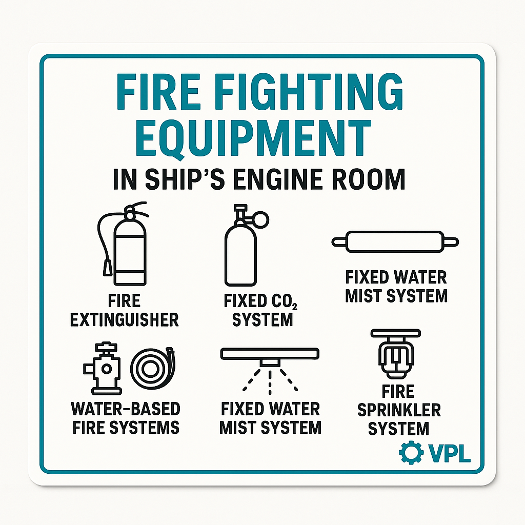
Firefighting Equipment in the Ship’s Engine Room
A ship’s engine room is one of the most fire-prone spaces onboard. Between high-temperature machinery, fuel lines, and abundant electrical circuits, you need robust detection and suppression tools. This guide breaks down the core firefighting systems—how they work, their types, and wiring/connection diagrams—to arm new apprentices with hands-on knowledge.
- Fire Detection & Alarm Systems
Understanding that a fire is starting is step one. Modern engine rooms use:
- Smoke detectors (optical or ionization) to spot early smoke
- Heat detectors (fixed-temperature or rate-of-rise) to sense abnormal temperatures
- Manual call points (“break-glass” E-stop buttons) for instant crew alert
- Central fire-alarm control panel with zones, annunciators, and sirens
The schematic below shows a typical detection loop:
[Smoke/Heat Detector]──┐
▼
[Fire Alarm Panel]──▶ [Bell/Siren]
│
[Manual Call Point]
Detectors and call points feed the control panel, which then drives alarms and interfaces with suppression systems.
- Fixed Fire-Suppression Systems
These automatic systems blanket the engine room when a fire is confirmed, cutting oxygen or cooling the space.
| System | Medium | How It Works |
|---|---|---|
| CO₂ Flooding | Carbon dioxide | Displaces O₂, smothering fire; requires room evacuation |
| Water Mist | High-pressure water | Ultrasonic nozzles create fine mist to cool and suffocate |
| Foam Sprinkler | AFFF or protein | Forms surface blanket on hydrocarbon fires |
| Inert Gas (IG) | N₂/Ar/CO₂ mix | Reduces O₂ while remaining safe for brief human exposure |
CO₂ cylinders sit in a bank outside the room; a solenoid release valve opens on alarm, and piping delivers gas through nozzles above machinery. Water mist and foam systems tie into seawater/foam concentrate pumps and distribute via dedicated risers and spray heads.\
2.1 CO₂ Flooding Connection Diagram.
   CO₂ Bottle Bank
          │
  [Solenoid Release Valve]
          │
    Main Distribution Pipe
   ┌──────────┴───────────┐
   │                      │
Nozzle A Nozzle B
When the solenoid is energized by the fire panel, it vents all cylinders, sending a pulse of CO₂ into the engine room.
2.2 Water Mist / Foam Sprinkler Diagram
[Sea Chest] → [Fire Pump] → [Foam Proportioner or Mist Pump] → [Riser] → [Spray Heads]
- Pump pressurizes seawater (and foam)
- Riser feeds manifold with branching spray heads positioned above hot machinery
- Nozzles atomize water/foam into a fine spray to rapidly cool and blanket fires
3. Portable Fire Extinguishers
Hand-held units let crew attack small blazes before they escalate. Four main types live in engine-room alcoves:
| Extinguisher | Band Color | Use Case |
|---|---|---|
| Dry Powder | Black band | Class A, B, C (wood, oil, gas) |
| Foam | Yellow band | Class A & B (oil, fuel spills) |
| Water (sea-water) | Red with white stripes | Class A only (paper/wood) |
| CO₂ | Black band | Class B & electrical equipment |
Extinguishers are mounted in cabinets at multiple levels, often near walkways and major fuel lines, with signage to guide newcomers.
4. Fire-Hydrant & Hose Reel System
A network of seawater-fed hydrants and hoses covers the engine room perimeter:
[Fire Pump]─┬─[Hydrant A]─(Hose & Nozzle) ├─[Hydrant B]─(Hose & Nozzle) └─[Hydrant C]─(Hose & Nozzle)
- Pump draws from sea chest or fire main
- Hydrant valves control flow to color-coded hoses
- Hose reels let crew swiftly unspool and direct spray onto a fire zone
Regular drills ensure apprentices know how to charge hoses, hold nozzles, and operate valves safely.
5. Engine-Room Sprinkler (Fine-Mist) Layout
Engine Room Fine-Mist Sprinkler Layout
Graphic: Fine-mist sprinkler nozzles positioned above generators, pumps, and gearboxes.
Use high-pressure mist to rapidly suppress oil fires without flooding the space.
6. Best Practices for Apprentices
- Label all detection and suppression piping clearly on your one-line diagrams.
- Test your CO₂ release solenoids and water-mist pump pressures monthly.
- Keep extinguisher gauges in the green and check hoses for kinks or damage.
- Conduct crew drills: alarm activation → evacuation → system reset.
Equipped with this overview, apprentices can visualize engine-room fire risks and the layered defenses designed to detect, suppress, and extinguish fires at sea.
3. Portable Fire Extinguishers
Hand-held units let crew attack small blazes before they escalate. Four main types live in engine-room alcoves:
| Extinguisher | Band Color | Use Case |
|---|---|---|
| Dry Powder | Black band | Class A, B, C (wood, oil, gas) |
| Foam | Yellow band | Class A & B (oil, fuel spills) |
| Water (sea-water) | Red with white stripes | Class A only (paper/wood) |
| CO₂ | Black band | Class B & electrical equipment |
Extinguishers are mounted in cabinets at multiple levels, often near walkways and major fuel lines, with signage to guide newcomers.
4. Fire-Hydrant & Hose Reel System
A network of seawater-fed hydrants and hoses covers the engine room perimeter:
[Fire Pump]─┬─[Hydrant A]─(Hose & Nozzle)
├─[Hydrant B]─(Hose & Nozzle)
└─[Hydrant C]─(Hose & Nozzle)
- Hydrant valves control flow to color-coded hoses
- Hose reels let crew swiftly unspool and direct spray onto a fire zone
Regular drills ensure apprentices know how to charge hoses, hold nozzles, and operate valves safely.
5. Engine-Room Sprinkler (Fine-Mist) Layout
Engine Room Fine-Mist Sprinkler Layout
Graphic: Fine-mist sprinkler nozzles positioned above generators, pumps, and gearboxes.
Use high-pressure mist to rapidly suppress oil fires without flooding the space.
6. Best Practices for Apprentices
- Label all detection and suppression piping clearly on your one-line diagrams.
- Test your CO₂ release solenoids and water-mist pump pressures monthly.
- Keep extinguisher gauges in the green and check hoses for kinks or damage.
- Conduct crew drills: alarm activation → evacuation → system reset.
Equipped with this overview, apprentices can visualize engine-room fire risks and the layered defenses designed to detect, suppress, and extinguish fires at sea.
Guide: Bilge Pump Wiring Basics
Keeping the boat dry, safe, and powered—one circuit at a time.
🧠 What’s a Bilge Pump?
A bilge pump removes unwanted water from the lowest part of a vessel (the bilge). It’s your first line of defense against flooding—and it needs to work automatically, manually, and reliably.
Key Components
- Bilge Pump: Submersible or diaphragm type
- Float Switch: Activates pump when water rises
- Manual Override Switch: Lets crew activate pump manually
- Fuse or Breaker: Protects the circuit
- Battery Source: Usually 12V or 24V DC
- Indicator Light (optional): Shows pump status
Wiring Layout Overview
Here’s a simplified diagram structure apprentices can sketch and memorize:
[Battery +] ──▶ [Fuse] ──▶+▶────▶ [Float Switch] ──▶ [Pump +]
│
└────▶ [Manual Switch] ──▶ [Pump +]
[Battery -] ─────────────────────────────────────▶ [Pump -]
Float switch path: Automatic operation
- Manual switch path: Crew override
- Fuse: Always near the battery for protection
- Ground: Direct to battery negative or bonded ground bus
🛠️ Installation Tips
- Mount pump low in bilge, but avoid debris traps
- Use marine-grade wire (tinned copper, AWG 14–12)
- Heat-shrink all connections and seal with dielectric grease
- Label wires clearly for future troubleshooting
- Test float switch with water before finalizing install
Common Mistakes to Avoid
- No fuse = fire risk
- Float switch wired after manual switch = pump won’t auto-run
- Shared ground with noisy electronics = interference
- Loose crimps = corrosion and failure
Apprentice Guide: Navigation Light Circuit Basics
See and be seen—wiring the lights that keep vessels safe at sea.
🧭 What Are Navigation Lights?
Navigation lights help vessels signal their position, direction, and status at night or in poor visibility. They’re legally required and must be wired for reliability.
Required Lights (for small powerboats)
- Red Port Light (left side)
- Green Starboard Light (right side)
- White Stern Light (rear)
- White Masthead Light (forward, high-mounted)
- All-Round White Light (combo for smaller boats)
🔌 Wiring Layout Overview
Here’s a simplified circuit sketch apprentices can build from:
[Battery +] ──▶ [Fuse] ──▶ [Navigation Light Switch]
├──▶ [Port Light +]
├──▶ [Starboard Light +]
├──▶ [Stern Light +]
└──▶ [Masthead Light +]
[Battery -] ───────────────────────────────▶ [All Lights -]
Single switch may control all lights, or use a multi-position switch for anchor vs underway modes
- Fuse protects the entire circuit or individual branches
- Ground returns can be shared or run individually
🛠️ Installation Tips
- Use marine-grade wire (AWG 16–14) and waterproof connectors
- Mount lights per COLREGS (height, angle, visibility)
- Label switch positions clearly (e.g., “NAV”, “ANCHOR”)
- Test visibility from 360° before finalizing install
- Consider LED upgrades for lower draw and longer life
Common Mistakes to Avoid
- Reversed polarity = no light or blown fuse
- Incorrect mounting angle = poor visibility
- Shared switch with other systems = confusion
- No fuse = fire hazard
📘 Apprentice Challenge
Design a circuit for a small vessel with:
- Separate switch positions for “Underway” and “Anchor”
- Proper fuse sizing
- LED light specs and wire gauge selection
Bonus: Explain how light placement affects visibility and legal compliance.
Guide: Shore Power Changeover Basics
Switching safely between onboard power and dockside supply.
🛥️ What Is Shore Power?
Shore power lets a vessel draw electricity from the dock—usually 120V or 240V AC—to run onboard systems without draining batteries or running a generator.
Changeover Options
There are three common methods:
🧭 Basic Manual Transfer Wiring
Here’s a simplified layout for a manual switch setup:
[Shore Power Inlet] ──▶ [Main Breaker] ──▶┐
├──▶ [Transfer Switch] ──▶ [AC Panel]
[Inverter Output] ─────▶ [Main Breaker] ──┘
Transfer switch selects either shore or inverter
- Breakers protect both inputs
- AC panel distributes power to loads
Installation Tips
- Use marine-grade AC cable (e.g., 10/3 or 12/3)
- Label all inputs and switch positions clearly
- Bond ground per ABYC standards (shore vs onboard)
- Test polarity and voltage before energizing
- Include reverse polarity indicator and ELCI breaker if possible
Common Mistakes to Avoid
- Backfeeding inverter into shore power = fire hazard
- No transfer switch = simultaneous power sources = danger
- Undersized wire = overheating
- Unlabeled panel = confusion and risk
📘 Apprentice Challenge
Sketch a shore power + inverter setup with:
- Manual transfer switch
- Proper breaker sizing
- Grounding and bonding paths
Bonus: Explain why automatic transfer might fail and how to troubleshoot it safely.