
Hey everyone! As a marine and shipyard electrician, I often work with three-phase generators—they’re the workhorses for powering heavy equipment on vessels, docks, cranes, pumps, and larger backup systems. Unlike single-phase gensets, three-phase ones deliver power in three waveforms (typically 208V, 480V, or 400V configurations), providing more efficient and balanced power for motors and big loads.
But when they fail—no output, unbalanced voltages, overheating, or unstable frequency—it can halt operations fast. I’ve troubleshot a few on boats and yard equipment, and the key is a systematic approach. This guide covers common issues step-by-step, with a focus on safety and real-world marine/industrial scenarios. Always consult your generator’s manual (brands like Cummins, Caterpillar, or Stamford vary), and if it’s under warranty or complex, call a certified tech.
Safety First
- De-energize: Disconnect loads, shut off fuel, and let it cool.
- Use PPE: Insulated gloves, safety glasses, and lockout/tagout.
- No-load testing initially to avoid damage.
- Work with a partner in confined spaces (like engine rooms).
- Verify no residual voltage with a multimeter before touching terminals.
Key Components of a Three-Phase Generator
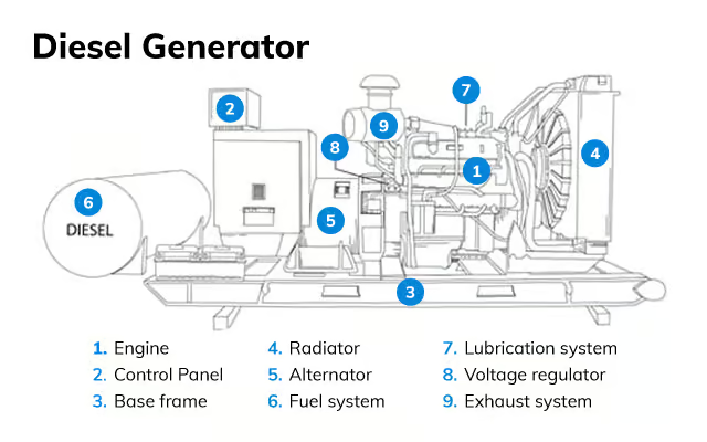
Understanding the parts makes troubleshooting easier. Here’s a typical breakdown:


(Diagrams showing labeled parts: Engine, alternator (stator/rotor windings), AVR, exciter, control panel, and star/delta connections.)
Common configs: Star (Wye) for higher voltage/neutral, Delta for higher current.


Step-by-Step Troubleshooting
Start simple and work deeper.
- Basic Checks (Won’t Start or Runs Rough)
- Fuel: Stale, water-contaminated (common in marine environments), low level, clogged filter/lines.
- Oil: Low level/pressure sensor trip.
- Battery/Electric Start: Charged? Connections clean?
- Air filter/exhaust: Blocked?
- Visual: Loose belts, leaks, debris in cooling vents.
- Runs But No/Low Power Output
- Test Voltages (No Load First): Use a multimeter on AC mode.


Measure:
- Line-to-Line (L1-L2, L2-L3, L3-L1): Should be equal (e.g., 480V ±5%).
- Line-to-Neutral (if wye): Equal lower voltage (e.g., 277V).
- Zero or very low? Proceed to excitation.
- AVR Issues: The Automatic Voltage Regulator is a frequent failure point.

Test sensing wires, output to exciter. Replace if faulty (similar to single-phase but often more robust models).
- Lost Residual Magnetism: “Flash” the field with a DC source (carefully—follow manual).
- Brushes/Exciter: Worn brushes, dirty slip rings, or exciter stator/rotor faults.
- Unbalanced Voltages One phase low/high? Common in 3-phase.


- Causes: Uneven loads, faulty winding, bad connection in star/delta links, or AVR sensing issue.
- Fix: Balance loads, check terminal connections, test winding resistance (should be equal across phases).
- Frequency/Surging Issues
- Engine RPM unstable: Governor adjustment, fuel issues.
- Overload: Remove loads and retest.
- Overheating or Shutdowns
- Cooling: Blocked radiators (salt buildup in marine!), low coolant.
- Ventilation: Poor airflow in enclosures.
- Overload or shorted windings.
Quick Reference Flowchart
Visual guides help on the job:

Advanced AI-driven techniques for fault and transient analysis in …
(Example fault analysis flowchart—adapt to your model.)
Pro Tips from the Field
- Use a phase rotation meter to confirm correct sequence.
- Log voltages under load for baselines.
- In marine settings: Check for corrosion on terminals—salt air is brutal!
- Preventive: Regular exciter checks, AVR calibration, and load bank testing.
Recently fixed a shipyard 3-phase unit with unbalanced output—it was a loose star point connection. 20 minutes and back online!
If you’ve got 3-phase generator war stories or need details on a specific brand, comment below. Stay safe and keep the power flowing
In-Depth AVR Troubleshooting: Diagnosing and Fixing Voltage Issues in Generators
Hey team! As a marine and shipyard electrician, the Automatic Voltage Regulator (AVR) is one of the most common pain points I’ve seen in both single-phase and three-phase generators. It keeps output voltage stable, but when it fails, you get no power, low/high voltage, surging, or unstable output—often stranding you on a job site or boat.
Building on my previous posts about generator troubleshooting and AVR replacement, here’s a detailed guide focused purely on diagnosing AVR problems. We’ll cover symptoms, testing methods, tools, and when it’s not the AVR. This is hands-on from real fixes I’ve done—stay safe, always no-load test first, and refer to your model’s manual!
Common AVR Failure Symptoms
Before testing, match your issue:
- No voltage output (0V at outlets, engine runs fine).
- Low voltage (e.g., 50-80V instead of 120/240V).
- High voltage (over 140/260V, risking damage to tools).
- Voltage surging/hunting (fluctuates wildly).
- Unstable under load (drops too much when adding power).


(Slides and videos showing typical no-power scenarios—AVR failure often looks like this.)
Other causes can mimic these (brushes, windings, lost magnetism), so systematic testing is key.
Tools You’ll Need
- Digital multimeter (AC/DC volts, ohms, continuity).
- 12V battery or drill battery (for flashing if needed).
- Screwdrivers, wire labels, flashlight.
- Optional: Oscilloscope for advanced waveform checks, but multimeter suffices for most.
Step-by-Step AVR Troubleshooting
Follow this order—start simple!
- Rule Out Basics First
- Check outlets/breakers: Reset GFCI or breakers.
- Test residual voltage: Run engine, measure AC at outlets (no load). Under 5-10V? Likely excitation issue (AVR or magnetism).
- Inspect brushes/slip rings (brushed models): Worn? Dirty? Clean with fine sandpaper.
- Visual AVR Inspection
- Access the AVR (remove end cover).
- Look for burnt smells, swollen capacitors, cracked boards, loose wires.


(Typical AVR boards—burn marks or damage are red flags.)
- Multimeter Tests on AVR
- Diode/Resistance Check (AVR removed or wires disconnected for accuracy):
- Set to diode mode or ohms.
- Test input/output terminals per manual—look for open/short circuits.
- Common: Probe excitation terminals (F+/F-) for continuity to brushes.
- Diode/Resistance Check (AVR removed or wires disconnected for accuracy):


(Hands-on multimeter testing—probe sensing wires, field output, etc.)
- Sensing Voltage: Run generator, measure AC input to AVR sensing terminals (usually 2 wires from stator)—should be proportional to output.
- Excitation Output: Measure DC volts from AVR to brushes while running (typically 10-50V DC building up).
- Flash the Field Test (If No Residual Voltage)
- Lost magnetism often fools you into blaming AVR.
- Briefly apply 12V DC to brushes while running (polarity matters—check manual). If voltage builds (even temporarily), AVR might be good—magnetism was the issue.
Troubleshooting Generator With No Power Output – AVR and Brush Replacement – Flashing the Field
(Flashing demo—common fix before replacing AVR.)
- Wiring and Schematic Check
- Compare connections to diagram—reversed wires fry AVRs.
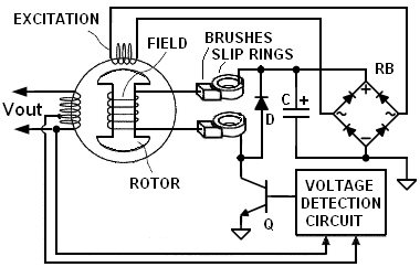

(Standard AVR wiring schematics—match your model’s terminals.)
When It’s NOT the AVR
- Bad capacitor (capacitor-excited models).
- Open/shorted stator/rotor windings (test resistance—should match specs).
- Engine RPM too low (frequency affects voltage).
- Overload or poor grounding.
Quick Troubleshooting Flow
Many pros use block diagrams for logic:

(AVR system block diagrams—trace from sensing to excitation.)
In one shipyard fix, low voltage was a faulty sensing wire—multimeter caught it quick. If tests point to AVR, replace as in my earlier guide.
Got a specific model or symptom? Share in comments—I can dive deeper. Keep those generators regulated! ⚡🛠️🌊