
Control a single light from two or more locations? That’s where 3-way and 4-way switches come in. Below you’ll find:
- A concise overview of each switch type
- Step-by-step wiring diagrams (ASCII) you can translate into client-ready graphics
- Guidance on when and where to use them
- Design tips for clear, branded blog visuals
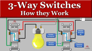
- 3-Way Switches
Control one fixture from two locations (e.g., top and bottom of a stair).
How It Works
- 4-Way Switches
Extend multi-location control beyond two points (e.g., three-way control at three doors).
How It Works
- Two 3-way switches bookend one or more 4-way switches.
- The 4-way effectively “crosses” or “straight-throughs” the travelers.
Wiring Diagram (ASCII) - [3-Way A]──T1──┐
- [4-Way]──T1──[3-Way B]
- [3-Way A]──T2──┘ └─T2──[3-Way B]
- 3-Way A: common to hot
- 4-Way in middle: four screws—two in, two out
- 3-Way B: common to load
Step-by-Step - Position your 3-way switches at the start/end of the run.
- Insert one or more 4-way switches between them, each in its own box.
- Run uninterrupted traveler pairs through all switches.
- On each 4-way, land the incoming travelers on the “input” pair of screws and the outgoing on the “output” pair.
- Maintain consistent traveler color coding end-to-end.
- Bond all grounds.
When to Use: - Three or more entry points to a room (e.g., large conference room)
- Multi-section corridors
- Outdoor lighting control at different access gates
- Graphic & Blog Design Tips
- Use color-coded wiring: black for hot/common, red/white for travelers, green for ground.
- Label each conductor at both ends.
- Provide a zoomed-in callout of traveler screw terminals.
- Overlay numbered steps with arrows on the drawing.
- Include a legend box with wire color, screw labels, and symbol keys.
- Stick to your brand’s color palette for borders and typography; keep the wiring colors standard.
- Offer downloadable SVGs so apprentices can toggle wire visibility.
- Beyond Basic Switching
- Smart multi-way switches: integrate dimming or remote control via Zwave/Wi-Fi.
- Common pitfalls: mixing up traveler pairs, forgetting to derate cable fill in multi-gang boxes.
- Testing: use a two-pole tester or voltage indicator to confirm traveler continuity before finalizing trim.
- Next-Level Blog Ideas
- How to convert a 3-way to a smart-enabled multi-way setup
- Calculating voltage drop over long traveler runs in marine environments
- Code compliance checklist for multi-gang installations
- Detailed 3-Way Switch Wiring Instructions
- Tools & Materials
- Marine-rated 12 AWG, 3-conductor cable plus continuous ground (tinned copper)
- Two 3-way switches (with one common screw and two traveler screws)
- Marine-grade cable glands, heat-shrink tubing, and dielectric grease
- Wire strippers, screwdrivers, voltage tester, fish tape.
Wire Color
Function
Black
Hot feed (to Switch A common)
White (re-marked)
Traveler 1 (to traveler screw)
Red
Traveler 2 (to traveler screw)
Bare/Green
Ground (bond to both boxes)
(Neutral stays at light fixture)
Neutral returns to panel - Wiring Diagram (ASCII)
- [Power Panel]
- │
- Black ──┐
- │ ┌───[Light Fixture]── Neutral
- [Switch A] │ │
- C ─── Common │ │
- T1 ──┐ Travelers ──┐ │ │
- T2 ──┘ └─[Switch B]── Common── Black to lamp
- T1 ──┐
- T2 ──┘
Step-by-Step
- Cut power at the panel and verify off with your tester.
- Pull 12 AWG, 3-conductor cable from the power source into Switch A’s box.
- Connect the black hot feed to the common (C) screw of Switch A.
- Land the red and re-marked white conductors under the traveler (T1, T2) screws of Switch A.
- Run that same 12 AWG cable from Switch A to Switch B.
- In Switch B’s box, land the red and re-marked white on its traveler screws.
- Connect Switch B’s common screw to the black lead going onward to the light fixture.
- Cap and tuck the neutral (white) in Switch A—neutrals don’t connect to 3-ways.
- Bond both metal boxes with the bare/green ground and land on each switch’s green screw.
- Seal cable entries with marine glands, apply dielectric grease on screws, and secure cover plates.
Detailed 4-Way Switch Wiring Instructions
Tools & Materials
- Marine-rated 12 AWG, 3-conductor cable plus ground (tinned copper)
- Two 3-way switches (start/end) and any number of 4-way switches (middle)
- Marine-grade cable glands, heat-shrink tubing, and dielectric grease
- Wire strippers, screwdrivers, voltage tester, fish tape
| Wire Color | Function |
|---|---|
| Black | Hot feed into first 3-way common |
| Red | Traveler conductor |
| White (re-marked) | Traveler conductor |
| Bare/Green | Ground |
| Black (from last 3-way) | Load to light fixture |
| Neutral stays at light fixture | Neutral returns to panel |
Wiring Diagram (ASCII)
[3-Way A]── Black common (hot in) │ T1┌┐T2 ┌──┐ ││ │4W│ T2└┘T1 └──┘ │ [3-Way B]── Black common (load out) │ [Light Fixture]
Step-by-Step
- De-energize circuit and confirm with a tester.
- Pull cable from power source to 3-Way A; connect black to its common.
- Tie red and re-marked white to 3-Way A traveler screws.
- Run continuous 3-conductor cable through each 4-way location, landing travelers on the “IN” pair of screws.
- On each 4-way, land the outgoing travelers on the “OUT” pair—maintain color consistency (red-white).
- Continue that cable run into 3-Way B, land travelers on its traveler screws.
- Connect 3-Way B’s common screw to the black conductor feeding the light.
- Bond all grounds in every box to switch green screws and box bodies.
- Cap neutral conductors in first and any middle boxes; only extend neutral to the fixture.
- Seal all entries, apply grease, and tighten covers.
Next-Level Tips
- For longer marine runs, calculate voltage drop and consider upsizing to 10 AWG.
- Use numbered wire labels at both ends for multi-switch runs.
- Combine diagrams with cut-away box views showing terminal screws—great for field-use cards.
- Offer an interactive SVG on your blog where apprentices toggle on/off each switch to see circuit paths.
- Include a brief safety call-out on lock-out/tag-out procedures—critical in marine electrical spaces.
Common Applications for 3-Way and 4-Way Switch Connections
3-Way Switch Circuits
- Hallways and Corridors
Control a single light or a bank of lights from both ends of a passageway for safety and convenience. - Staircases
Turn landing lights on or off from the top and bottom of the stairs to prevent fumbling in the dark. - Garages and Workshops
Operate overhead lighting from both inside the garage and at the entry door. - Outdoor Entry and Porch Lights
Switch porch or patio lights from the door and from an interior foyer. - Master Bedrooms
Control ceiling fans or overhead fixtures from the main entrance and at bedside for late-night convenience. - Kitchen Islands and Peninsulas
Toggle task lighting from two opposing ends of a long island or counter run.
4-Way Switch Circuits
- Long Hallways with Multiple Entrances
Place 4-way switches between two 3-ways so you can control lighting from three or more points along an extended hallway. - Large Family or Media Rooms
Install 4-ways to let you switch recessed cans or multi-zone fixtures from several doorways and seating areas. - Multi-Car Garages and Workshops
Manage different lighting banks (left, right, center) from multiple access points. - Conference Rooms and Lobbies
Offer seamless control of overhead fixtures from main entrances, side doors, and presentation areas. - Outdoor Landscape or Perimeter Lighting
Run control points at entry gates, doorway exits, and a central control panel to manage exterior lights.
Additional Considerations
- Label all traveler conductors clearly at each switch box to avoid confusion during installation and troubleshooting.
- Use consistent wire-marker colors or numbered flags so apprentices and future electricians can trace circuits quickly.
- For dimming or multi-zone LED systems, pair 3- and 4-way wiring with compatible electronic dimmers or smart switches designed for multi-location control.
- In marine or industrial settings, apply the same principles but choose corrosion-resistant switches and tinned copper conductors.
- Always follow the latest electrical code requirements for box fill, conductor sizing, grounding, and installation practices.
Here are a few creative extensions you might explore next:
- Integrating motion sensors into a 3-way loop for automated stair lighting.
- Combining low-voltage landscape lighting with a 4-way control for “scene” switching.
- Designing a training card that overlays a transparent switch legend on your graphic for hands-on apprentice drills.