
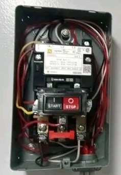
A motor starter combines switching and protection functions to safely start, run, and stop a motor. At its core, it has two main parts:
- A contactor that makes/breaks power to the motor
- An overload relay that trips if the motor draws too much current
The starter’s control circuit uses pushbuttons and auxiliary contacts to energize the contactor coil, which latches in until a stop command or overload trip opens it.
Core Components
Contactor
An electromechanical switch (heavy-duty relay) with:
- A coil (terminals A1/A2) powered by the control circuit
- Main power contacts (e.g., L1–T1, L2–T2, L3–T3 on a 3Φ starter)
- Auxiliary contacts (NO/NC) for holding circuits or interlocks
Overload Relay
Monitors motor current and trips if sustained overcurrent occurs. Types:
- Thermal (bimetallic): trips on heat build-up
- Magnetic: trips on magnetic field strength
- Electronic: solid-state sensor with adjustable setpoints
Pushbuttons & Auxiliary Contacts
Hold-in Contact (NO auxiliary) wired parallel to the Start button so the coil stays energized after you release Start
Stop Button (NC) in series with coil—breaks the circuit to stop the motor
Start Button (NO) momentarily energizes the coil
Single-Phase Starter Connection
Use a 2-wire supply (L & N). The contactor’s three poles are paralleled so phase-loss detection still works.
ASCII Diagram:
Power Side Control Side
L ────┬─────┬────( L1 ) Contactor ──┐
│ └────( L2 ) Contactor ─┐│
│ └────( L3 ) Contactor ── Motor
│
N ─────┘
Control Circuit
L ──[ Stop (NC) ]──[ Start (NO) ]──+──(A1) Contactor Coil
│
+──[ Aux (NO) ]────┐
└──(A2) back to N
How it works:
- Press Start
- Coil A1/A2 energizes → closes main contacts → motor runs
- NO-aux closes in parallel with Start → you release Start → coil stays on
- Press Stop → opens NC stop button → coil de-energizes → motor stops
Three-Phase Starter Connection
Uses three incoming lines (L1, L2, L3) and a four-wire control circuit.
ASCII Diagram:
Power Side Control Side
L1 ────┬─────(1/L1) Contactor ──┐
L2 ────┼─────(3/L2) Contactor ─┐│
L3 ────┴─────(5/L3) Contactor ─┘│
├─ Motor
┌┴─┐
T1(2)─┐ T2(4)─┐ T3(6)─┐ │
│ │ │ │
Overload Relay in series └───────────
Control Circuit
+240V (or 24VDC) ──[ Stop NC ]──[ Start NO ]──+──(A1) Coil
│
+──[ Aux NO ]──┐
└──(A2) return
Key points:
- Overload relay sits between contactor and motor, so tripping it cuts power.
- Feed the coil through Stop, Start, and the NC winding contact of the overload relay for combined stop/overload protection.
- Overload vs. Contactor
- Overload: Protects motor windings from overheating due to prolonged overcurrent. Adjust to ~115% of motor full-load current; trips after a time delay.
- Contactor: High-current switch that opens/closes the motor’s power circuit under remote control. Built for frequent operation, with arc suppression and contact materials suited for motor inrush currents.
- Beyond Direct-On-Line
- Once you’ve mastered basic DOL starters, you can explore:
- Reversing Starters (two contactors swap L1/L2 to reverse rotation)
- Star-Delta (reduced-voltage start)
- Soft-Starters & VFDs (smooth acceleration, torque control)
- Always size overload relays, contactors, and control wiring per the motor’s horsepower and the National Electrical Code (NEC) or local marine rules.
- Steps & Resources
- • Marine-rated enclosures and corrosion-proof contactors
- • Anchor chain installation for GFCI and ground-fault protection in bilge
- • Code references: NEC Article 430 (motors), Article 430.32 (starters), and UL 508 (industrial controls)
- • Sample field-ready wiring templates you can brand for your apprentices.